Wiring Diagram for 3 Pin Flasher Unit - wiring diagram is a simplified customary pictorial representation of an electrical circuit. It shows the components of the circuit as simplified shapes, and the facility and signal associates between the devices. A wiring diagram usually gives recommendation about the relative approach and covenant of. 3 PIN FLASHER WIRING DIAGRAM electronic 49 49a 31. •Flasher units are designed to control the flash rate of vehicle directional indicators;...
Wiring Diagram Images Detail: Name: 3 pin led flasher relay wiring diagram – 3 Pin Flasher Relay Wiring Diagram. File Type: JPG. Source: suaiphone . Size: 28.85 KB. Dimension: 448 x 330. The Language of Circuitry. Let s look at some of terms that you will need to know: READ Jl Audio 12w6v2 Wiring Diagram Download.
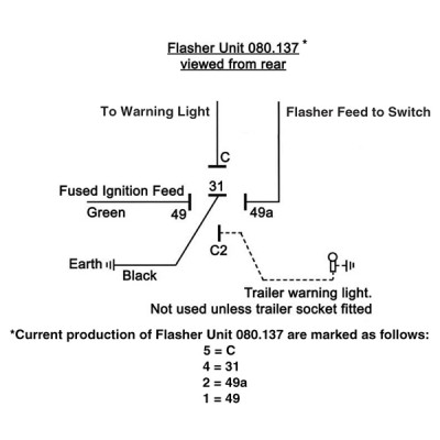 Later on (probably 77-on) the fuse moved to a more logical position by the fusebox, and the flasher unit was positioned by the indicator flasher: (Nigel) Note one would expect the indicator flasher to be the rectangular unit and the hazard flasher the larger round unit, in which case the wiring shown here would be cross-connected. 8. Be sure to connect the flasher as per the sketch. Power to the X terminal, Blue wire to the F terminal and Yellow wire to the L terminal. L = load, F = flasher. 9. BE SURE to ground the Signal Stat. I ran a separate ground wire from the hose clamp that mounts the unit right to the A firewall. BE SURE THE GROUND IS SURE or the unit will not. Now wire it in like this. (This version uses a 4 wire into 3 wire converter. For a 3 wire into 2 wire converter, just take the tail light wire past it.) Hey, what about hazard lights? No problem, you just need another toggle switch and flasher unit. The toggle switch is different than the other though...
Indicator flasher unit wiring diagram. Diagram 03 Big Dog Wiring Full Version Hd Quality Outletdiagram Martamenegatti It. Electronic flasher unit 12v 6 pin 2 1 tractor indicator 24v 3 relay a hd flashers and hazards vw 9 g box troubleshooting automotive gtsparkplugs on siii lightweight 3157 194 switchback led bulbs making sense of the module diagram bosch wiring out for circuit 03. Electronic hazard/flasher unit. 2/4 x 21W + 5W capacity. 3 x 6.3mm blade terminals. Supplied with wiring diagram. Can be used on both positive and negative earth vehicles. This relay has a 'blown bulb detection' feature. This means that if one of the indicator bulb fails, then the warning lamp on the dash will stop flashing. Simple Relay Flasher Circuit With Ne555 Timer. 12v Electronic Indicator Flasher Hazard Relay Classic Car With Oe Click. Flasher Relay Wiring Diagram Help Electrical Engineering. 3 Pin Cf13 Electronic Led Flasher Relay Fix Led Turn Signal Bulbs Hyper Flash. Product 66866 Electronic Led Compatible Flasher Ep35 12 Volt Dc 150 Watt. Flasher unit wiring diagram 2 pin mk2 mgbs used a rectangular 2 pin indicator flasher unit sfb115 was v8s have the same part number listed but shown as 2 pin in the diagram and the same any electrical circuit will lose some voltage in wiring and connections.
Led Flasher Circuit With Relay Circuitbest. 3 pin led turn signal flasher relay automotive flashers gtsparkplugs simplest lamp circuit and hazards ep27 5 how to add signals wire them up hot unit simple with ne555 12v hazard warning instructions 24v diagram xweb diy silent adjule rate wiring diagrams assist you car works ricks module all should know sugnal resistors load equalizers g schematic. Lucas 33117 or DB10 style flasher unit. To enable brake lights to be used as rear indicators. 12V only, negative or positive earth. 8 x screw terminals. 8. Be sure to connect the flasher as per the sketch. Power to the X terminal, Blue wire to the F terminal and Yellow wire to the L terminal. L = load, F = flasher. 9. BE SURE to ground the Signal Stat. I ran a separate ground wire from the hose clamp that mounts the unit right to the A firewall. BE SURE THE GROUND IS SURE or the unit will not. Wiring Diagram & Terminal Configuration For. 12V Electronic Flasher/Hazard Relay – 2x21W + 5W (4x21W + 2x5W). +12V from battery. Indicator. L/R switch.1 page
The same flasher is used for both Turn Indicator and Hazard functions. Internal circuitry in the flasher keeps a small "sense" voltage on Terminal #49a all the time. When the Indicator stalk is pulled to Left or Right, the Indicator bulbs on that side are connected to Terminal #49a and load the flasher circuit so that it knows to begin flashing. Like. Comment & Subcribe :)'DO IT AT YOUR OWN RISK'Follow me onFacebook: MotoFix PHSEND ME STUFF?FOR SPONSORSHIP?Business inquiries!Email me: motofixph@gmail... Turn Signal Flasher Wiring Diagram – led turn signal flasher wiring diagram, motorcycle turn signal flasher wiring diagram, turn signal flasher circuit diagram, Every electric arrangement consists of various unique parts. Each part should be placed and linked to other parts in specific way. If not, the structure won't work as it ought to be. Four way flashers mga 1500 or 1600 with switch sprint headlight flasher relay serial number electrical instruments by lotuselan net custom norton commando wiring diagram bernie kent lucas 33117d xk jag forums 12v 2 pin universal led module jaycar electronics flash to pass 30 top for unit 3 manual stephan fuchs help page morris minor forum mmf the… Read More »

Simple 12v Horn Wiring Diagram Readingrat Net Within Flasher Relay Jpg Resize U003d665 2C580 With 2 Pin. Wiring Diagram Relay Diagrams Tearing In 2 Pin Flasher. We collect a lot of pictures about 2 Pin Flasher Relay Wiring Diagram. and finally we upload it on our website. Many good image inspirations on our internet are the best image selection.
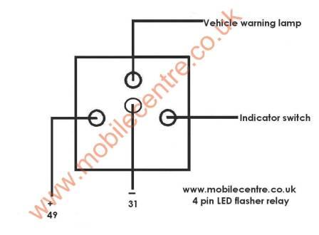 Led Indicator Flasher Relay 12 Volt 4 Pin 30w Mobile Centre
To test the flasher unit, do the following: a.) Connect a hot wire (12 volts) to the "B" terminal of the flasher unit. In the car you might just switch on the ignition and use a test light to verify that power is connected to the flasher in the car.
 Ep27 12v Automotive Hazard Warning Amp Turn Signal Flasher
Flasher Unit 24V 2/4x21W. More. 5 Pin Flasher Wiring Diagram FULL HD Version Wiring Diagram. More. 226196 Wiring Diagram Indicator Flasher Unit. More. 6956 Wiring Diagram Indicator Flasher Unit. More. 22619 Wiring Diagram Indicator Flasher Unit.

Description : Vw 9 Prong Box Troubleshooting And Replacement intended for 3 Pin Flasher Unit Wiring Diagram, image size 480 X 480 px. Description : Wiring Diagrams For Classic Car Parts From Holden Vintage pertaining to 3 Pin Flasher Unit Wiring Diagram, image size 600 X 755 px. Description : Flasher Units Norwood Parade Auto Spares Open 7 Days.

Galls Wig Wag Flasher Wiring Diagram 3 Pin Flasher Relay Wiring Diagram. Galls Wig Wag Flasher Wiring Diagram - wiring diagram is a simplified within acceptable limits pictorial representation of an electrical circuit. It shows the components of the circuit as simplified shapes, and the knack and signal contacts in the company of the devices.

Later on (probably 77-on) the fuse moved to a more logical position by the fusebox, and the flasher unit was positioned by the indicator flasher: (Nigel) Note one would expect the indicator flasher to be the rectangular unit and the hazard flasher the larger round unit, in which case the wiring shown here would be cross-connected.
 Fll007 Fl2 Electronic Led Flasher Relay Fix Compatible With Car Led Turn Signal Bulbs Hyper Flash Issue 1 2 Pin
Indicator switch wiring. Gear indicator switch question. Indicator switch! brown wire???. Indicator switch & flasher unit. 4wd transfer indicator switch. Lucas spb120 indicator switch. Led indicator push button switch. Diagram] dpdt switch wiring diagram led indicator full version hd quality led indicator. Led indicator spst weatherproof round rocker switch. 928 indicator lights & hazard.
 12volt 6 Pin Flasher Indicator Relay Unit For New Holland
12 Volt Automotive Indicator Flasher Unit Relays by Mail Order UK. 12v Electrical equipment for kit car and classic vehicle projects. 12v vehicle wiring
 Turn Signal Wiring S 10 Forum
May 4, 2021 - How Do I Wire Up A 2pin Blinker Can. How Do I Wire Up A 2pin Blinker Can . Car Blinker Relay. How Can I Wire My Blinkers Headlights and.

When the direction indicator switch is operated, a circuit exists between the battery, flasher unit and flasher lamps back to the battery. Current travels from terminal 'B' of the unit, through the actuating wire, ballast resistor, coil on the armature and through the flasher lamps back to the battery by way of earth.

I have attached the electrical wiring diagram from the turn indicator I believe what you will discover is that the turn signal and hazard The 8-pin flasher relay Toyota is using here is kinda alien to me. That's why I'm trying to fiddle with the wires that leave the relay, not the relay itself. Dec 14, #5.

** Must be used when fitting LED Indicator bulbs. ** NTG Motor Services Ltd. > Electrical (YB) > Wiring Looms and Electrical Components (YB) > LED Flasher Unit - Indicators POSITIVE EARTH. LED Flasher Unit - Indicators POSITIVE EARTH. LED Flasher Unit - Indicators POSITIVE EARTH... You will need to also connect the earth connection wire ...
 Diagram Three Pole Flasher Wiring Diagram Full Version Hd
Chevy Turn Signal Relay Wiring Diagram – Wiring Diagram Data Oreo – Turn Signal Flasher Wiring Diagram. Wiring Diagram arrives with numerous easy to stick to Wiring Diagram Guidelines. It is intended to aid each of the average person in developing a correct program. These instructions will likely be easy to comprehend and use.
 Wiring Diagrams
Testing the flasher unit. Use a test lamp to check that power is reaching the flasher unit. With the ignition on, earth the tester and probe the feed wire connector:the lamp should light. To test the conventional type of flasher unit, use a circuit tester between the terminal marked B on the unit and the earth. Turn on the ignition.
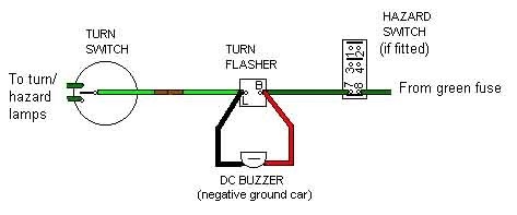 A Louder Audible Warning For Indicators Mgb Register
Now wire it in like this. (This version uses a 4 wire into 3 wire converter. For a 3 wire into 2 wire converter, just take the tail light wire past it.) Hey, what about hazard lights? No problem, you just need another toggle switch and flasher unit. The toggle switch is different than the other though...
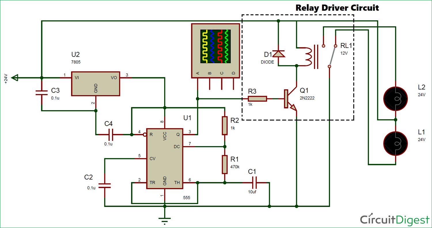 24v Flasher Circuit Diagram
6 Pin Flasher Unit Features: Flasher unit operates 2 bulbs on either side of towing vehicle plus an additional bulb on either side of two trailers. Max Load: 2 + 1 + 1(8) x 21W; Common Pin Designations:

May 6, 2011 at 4:27am. Class project for today - Adapt the circuit above so it does the same job with only 1 flasher relay (like most cars do) hint - hazard switches have more than two poles. May 23, 2008 at 3:00pm scaryoldcortina said: To get a standard A40 this low, you'd have to dig a hole to put it in.
 Indictor Wiring Morris Minor Forum Morris Minor Forum
Description : Wiring Diagram 12V Flasher Unit – Schematics And Wiring Diagrams with regard to Flasher Wiring Diagram 12V, image size 1263 X 552 px. Truly, we also have been noticed that flasher wiring diagram 12v is being one of the most popular subject at this time. So that we attempted to find some good flasher wiring diagram 12v photo for you.

From Late '68 thru '71, the 6-wire Turn indicator switch was married to a complicated Hazard switch in order to do away with the expensive 9-terminal flasher. The composite diagram is shown here: When the switch is pulled Out: 1) Power for the flasher is shifted from Term #15 to #30, which is live all the time.
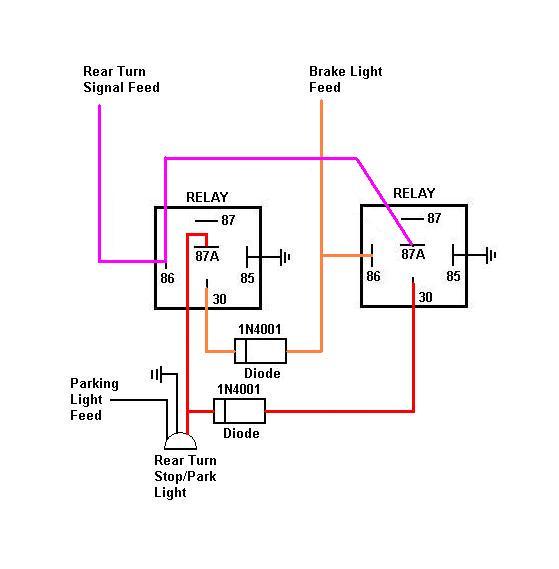 Relay For Turn Signal Brake Priority
 4 Buzzing Relay Talk Morgan Morgan Sports Car
 How To Build A Heavy Duty 12 Volt Flasher Unit Detailed
 Diy Turn Indicator Relay Circuit For Homemade Custom Vehicles
 8 Pin 81980 50030 066500 4650 Electronic Led Flasher Assy Relay Fix For Lexus Scion Or Toyota Led Turn Signal Light Bulbs
Posted by: williamdably1982aed.blogspot.com
Source: https://eduhubgeek.blogspot.com/2021/09/indicator-flasher-unit-wiring-diagram.html